Cables and Connections
Using the correct cable on your solar measuring instruments is very important. The lower the impedance value (resistance) of the cable, the lower the voltage drop over the cable! Choosing the correct insulation material makes a big difference. A constant exposure to UV radiation could cause the cable to become brittle and it must remain flexible at low temperatures.
Kipp & Zonen uses a low impedance cable with insulation types to withstand years of UV exposure. It is suitable for prolonged installation at extreme temperatures without experiencing any problems. This cable can easily be recognized by its yellow colour.
Each of our solar radiation instruments are equipped with the same cable and connector types. This section provides you with the specifications of the cable and connector, to either purchase them locally or extend current cable lengths.
We use one type of cable with three different numbers of wires inside:
-
2 wire cable
-
4 wire cable
-
8 wire cable
The type of instrument and the fitted temperature sensor decide the cable type:
x = one cable used
xx = two cables used
(x) = no connector, cable is captive in housing
|
|
2-wire |
4-wire |
8-wire |
| CMP3, CMP6, CMP10, CMP11 |
Pyranometer |
x
|
|
|
| CMP21 / 10K, CMP22 / 10K |
Pyranometer |
|
x
|
|
| CMP21 / PT-100, CMP22 / PT-100 |
Pyranometer |
|
|
x
|
|
SMP3, SMP6, SMP10, SMP11, SMP21, SMP22
|
Smart Pyranometer |
|
|
x |
| CMA6 |
Albedometer |
|
x
|
|
| CMA11 |
Albedometer |
|
x
|
|
| CGR3 / 10K, CGR4 / 10K |
Pyrgeometer |
|
x
|
|
| CGR3 / PT-100, CGR4 / PT-100 |
Pyrgeometer |
|
|
x
|
|
SGR3, SGR4
|
Smart Pyrgeometer |
|
|
x |
| CHP1 |
Pyrheliometer |
|
|
x
|
|
SHP1
|
Smart Pyrheliometer |
|
|
x |
| CSD3 |
Sunshine Duration |
|
|
x
|
| CUV5 |
UV Radiometer |
x
|
|
|
| SUV5, SUV-A, SUV-B, SUV-E |
UV Radiometer |
|
|
x
|
| UVS A-T, UVS B-T, UVS-E-T, UVS-AB-T, UVS-AE-T |
UV Radiometer |
|
|
x
|
| CNR2 |
Net Radiometer |
|
x
|
|
| CNR4 |
Net Radiometer |
|
|
xx
|
| CNF4 (2 versions in circulation) |
Ventilation Unit |
|
x
|
x |
| CVF4 (2 versions in circulation) |
Ventilation Unit |
|
x |
x
|
| NR Lite2 |
Net Radiometer |
(x)
|
|
|
| SP Lite2 |
Silicon Pyranometer |
(x)
|
|
|
| PQS1 |
Par Quantum Sensor |
(x)
|
|
|
| DustIQ |
Solar Monitoring System |
|
x |
|
Cable Specifications
|
2-wire
Li2YD11Y |
4-wire
Li2YD11Y |
8-wire
Li2YD11Y |
| AWG |
24 |
24 |
26 |
|
Number of strands
|
7x 0.2mm tinned copper
|
7x 0.2mm tinned copper
|
7x 0.15mm tinned copper
|
| Wire insulation |
PE |
PE |
PE |
| Wire thickness |
1.2 mm |
1.2 mm |
0.9 mm |
|
Shield
|
Spiral wrap tinned copper 0.15mm,
95% nominal optical coverage
|
Spiral wrap tinned copper 0.15mm,
95% nominal optical coverage
|
Spiral wrap tinned copper 0.15mm,
95% nominal optical coverage
|
| Cable insulation |
PUR |
PUR |
PUR |
| Cable thickness |
5 mm |
5 mm |
5 mm |
| Cable color |
Yellow RAL 1021 |
Yellow RAL 1021 |
Yellow RAL 1021 |
| Impendance |
~82 Ω/km at 20°C |
~82 Ω/km at 20°C |
~150 Ω/km at 20°C |
| Isolation resistance |
>1000 MΩ/km |
>1000 MΩ/km |
>1000 MΩ/km |
| Capacity |
~85nF/km |
~85nF/km |
~100nF/km |
Connector Specifications
| Brand |
Binder |
| Series |
712 |
| Part number |
99-0401-10-02 (2 pins) |
| Part number |
99-0409-10-04 (4 pins) |
| Part number |
99-0425-10-08 (8 pins) |
Calculating errors due to cable length:
Once the instrument is connected to the data logger the next schematic shows how the impedance (resistance) affects the measurement.
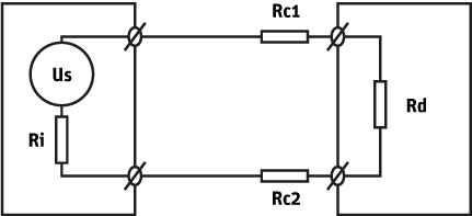
Us = sensor voltage (output of the instrument)
Rc1,2 = Cable wire resistance
Rd = Data logger impedance
Ri = Sensor impedance
The sensor impedance (Ri) is specified on the Calibration Certificate issued with all calibrated instruments (for example 75Ω for a CMP 21).
The impedance of both wires (RC1 and RC2) can be calculated when cable length and cable impedance are known (Rcx= cable impedance x cable length).
The CMP 21in combination with a 10k thermistor uses a 4-wire cable with an impedance of 82Ω /km (or 0.082Ω/meter).
The data logger used should be have HIGH impedance inputs, Rd = >1 MΩ.
If we would like to know what the additional error for a CMP 21 in combination with a 10k thermistor using 50 meter cable at 10mV output logged by the data logger, we just calculate the actual instrument output voltage using the next formula:
URd = Us x Rd / (Rd + Ri + Rc1 + Rc2)
10mV = Us x 1MΩ / (1MΩ + 75Ω + 4.1Ω +4.1Ω)
Us = 10.0008mV
This means a voltage drop of 0.8µV over the entire 50m cable.
The error using a 50m cable therefore is < 0.01%
Note: When the body temperature is measured with a 10K thermistor, the readings are affected by the cable length. A Pt-100 sensor in 4-wire mode is compensated for the wire resistance, so no additional error occurs.
Extending cable length
It can happen that your cable is too short to connect the instrument to the data logger.
Solution would be:
-
Order the correct connector and cable length locally using the information above and create your own cable.
-
Order the correct cable and connector assembly from Kipp & Zonen (contact your local Kipp & Zonen distributor for pricing information).
-
Extending your current cable using a junction box and an additional length of cable (both purchased locally). Ensure that the Junction box is metal, so that the cable shield is maintained, and is all-weather resistant if used outdoors.
Modifying old instruments:
Older instrument could have a different connector from those mentioned above, or a fixed cable with no connector. We have conversion kits to modify the instrument housings and make them compatible with the new cables and connectors. Please contact your local distributor for pricing information.
Note: Most conversions are by default performed using the 8-pin version due to the fact that the old instrument could have a 2, 4 or 8 wire cable fitted. This largely depends on the temperature sensor inside.
It is important to also order the matching 8 wire cable of the correct length (even though there might only be 4 wires connected to the instrument).
After modification, please download the latest version of the instrument Instruction sheet from our website, for the colour and wire information.